Astra Wireless Documentation
  • Technical documentation
    • Astra Quanta⁣ Technical User Manual
      • Introduction⁣⁣⁣⁣⁣⁣⁣
        • Key Features⁣⁣⁣⁣⁣
        • Hardware Platform⁣⁣⁣⁣⁣
        • Power Supply⁣⁣⁣⁣⁣⁣
        • Lightning⁣ ⁣protection unit⁣⁣⁣⁣⁣
        • Packing list⁣⁣⁣⁣⁣⁣⁣
      • Planning considerations⁣⁣⁣⁣⁣⁣⁣
      • Link pre-configuration in the lab⁣⁣⁣⁣⁣
      • Installation
      • Operation & Administration⁣⁣⁣⁣⁣
        • Web GUI access⁣⁣⁣⁣
        • Dashboard⁣⁣⁣⁣
        • General settings⁣⁣⁣⁣⁣
        • Security settings⁣⁣⁣⁣
        • Radio settings⁣⁣⁣⁣
        • Network settings⁣⁣⁣⁣⁣
        • Switch Settings
        • SNMP settings⁣⁣⁣⁣
        • Spectrum Analyzer⁣⁣⁣⁣⁣
        • Antenna Alignment Tool⁣⁣⁣⁣⁣
        • Maintenance⁣⁣⁣
        • Instant DFS⁣⁣⁣⁣
        • Graphs⁣⁣⁣⁣
      • Troubleshooting⁣⁣⁣⁣⁣⁣⁣⁣⁣
    • Astra Evolution Technical User Manual
      • Introduction⁣⁣⁣⁣⁣⁣
        • Key Features⁣⁣⁣⁣⁣⁣⁣
        • Hardware Platform⁣⁣⁣⁣⁣⁣⁣⁣
        • Power supply⁣⁣⁣⁣⁣⁣⁣
        • Lightning protection unit⁣⁣⁣⁣⁣⁣⁣⁣⁣⁣⁣
        • Synchronization unit⁣⁣⁣⁣⁣⁣⁣
        • ⁣⁣⁣Packing List
      • Planning considerations⁣⁣⁣⁣⁣⁣⁣⁣⁣
      • Link Pre-configuration in the lab⁣⁣⁣⁣⁣⁣⁣⁣⁣
      • Installation⁣⁣⁣⁣⁣
      • Operation & Administration⁣⁣⁣⁣⁣⁣⁣
        • Web GUI access⁣⁣⁣⁣⁣⁣
        • Device Status⁣⁣
        • Basic Settings⁣⁣⁣⁣⁣
          • System Settings⁣⁣⁣⁣⁣⁣
          • Network Settings⁣⁣⁣⁣⁣⁣⁣
          • Link Settings⁣⁣⁣⁣⁣⁣
          • Static Links⁣⁣⁣⁣⁣
          • MAC Switch⁣ ⁣
          • IP Firewall
          • SNMP
          • QoS Options⁣⁣⁣⁣⁣⁣
          • Traffic Shaping⁣⁣⁣⁣⁣⁣⁣
          • Extra Commands⁣⁣⁣⁣⁣⁣
        • Maintenance
        • Spectrum Analyzer
        • DFS
        • Command Line
      • Troubleshooting⁣⁣⁣⁣⁣⁣
        • No access to the local unit⁣⁣⁣⁣⁣
        • The wireless link cannot be established⁣⁣⁣⁣⁣
        • The wireless link is established, but there is no access to the remote device⁣⁣⁣
        • The wireless link throughput is lower than expected⁣⁣⁣
        • Common errors in configuration⁣⁣⁣⁣
        • Emergence Repair Console⁣⁣
        • Unicast-flood detection⁣⁣⁣⁣
    • AstraFleX⁣ Technical User Manual
      • Getting started with AstraFleX User Manual
      • ⁣⁣IP-address format
      • General Purpose Command Set
      • Layer 2 commands set -PHY and MAC
        • ⁣prf ⁣command
        • ⁣⁣lag command (Link Aggregation )
        • ⁣⁣svi command
        • ⁣⁣ltest (radio link test)
        • macf command (addresses mapping)
        • ⁣⁣arp command (ARP protocol)
        • ⁣⁣switch command
        • ⁣⁣dfs (Dynamic Frequency Selection)
        • ⁣⁣lldp command
        • ⁣⁣mint command
        • ⁣⁣rfconfig command
      • ⁣⁣Layer 3 Command set – IP Networking
        • ⁣⁣Ifconfig command (interfaces configuration)
        • tun command (tunnels building)
        • qm command (QoS configuration)
        • ⁣⁣route command (static routes configuration)
        • ⁣⁣arip command
        • ⁣⁣OSPF command
        • ARDA (Aqua Router DAemon)
        • ⁣⁣netstat command (Network statistics)
        • ⁣⁣ipfw command (IP Firewall)
          • ⁣⁣PCAP-filters
        • ⁣⁣loadm command (load meter)
        • ⁣⁣rpcapd command (Remote Packet Capture)
        • ⁣⁣snmpd command (SNMP daemon)
        • ⁣⁣td command (Telnet daemon)
        • ⁣⁣nat command (Network Address Translation)
        • ⁣⁣trapd command (SNMP Traps support)
        • dhcpd command (DHCP Server)
        • ⁣⁣dhcpr command (DHCP relay)
        • dhcpc command (DHCP Client)
        • ⁣⁣vrrp command (VRRP server)
      • ⁣⁣Other commands
    • ⁣NEXT Monitoring System Technical User Manual
      • Description⁣ and operational principles
      • Installation
      • Configuration⁣⁣ ⁣and⁣ management⁣
        • Wireless⁣ ⁣⁣devices preparation
        • Accounts⁣ and user groups
        • Devices⁣ ⁣and links
        • Incident⁣ ⁣⁣management
        • System⁣⁣ ⁣configuration
      • Monitoring⁣ ⁣and management
        • R⁣ep⁣o⁣⁣rts
        • Devices
        • ⁣⁣Incidents
        • MAP
      • Technical support
  • White⁣ papers
    • MINT ⁣⁣⁣technology
    • Dynamic ⁣⁣Frequency ⁣⁣Selection
    • ⁣⁣RADIUS authentication for admin users
    • Security in Astra Wireless Devices
    • ⁣⁣Performance of the Astra Wireless devices
      • Astra Quanta
        • ⁣⁣Thr⁣⁣⁣oughpu⁣t⁣⁣⁣⁣⁣⁣
        • ⁣Packet ⁣⁣performanc⁣e⁣⁣⁣⁣⁣
      • Astra Evolution
        • H22 platform
          • Packet ⁣⁣⁣perfor⁣mance⁣⁣
          • Throug⁣hput⁣⁣⁣⁣⁣⁣
        • H16 platform
          • Packet⁣⁣ ⁣perfor⁣mance⁣⁣
          • ⁣⁣⁣⁣⁣⁣Throug⁣hput⁣⁣⁣⁣⁣⁣⁣
    • ⁣⁣⁣Link ⁣⁣⁣aggregation, balancing and redundancy
      • Astra Evolution
        • Redundancy ⁣⁣⁣with Failover option
        • Redundancy w/o aggregation and AstraMUX
        • Redundancy⁣⁣⁣ ⁣with aggregation and w/o AstraMUX
        • Redundancy ⁣⁣with AstraMUX
        • Full⁣ Duplex
      • Astra Quanta
        • Aggregation ⁣with redundancy ⁣based on⁣ LACP
        • Redundancy⁣⁣⁣ ⁣based ⁣on STP
        • ⁣Redundancy⁣⁣ based on⁣ OSPF
        • ⁣Redundancy with Evolution
    • Beamforming⁣ ⁣technology
    • ⁣⁣⁣Remote ⁣⁣⁣L2 management of Evolution via CLI
    • ⁣⁣⁣Remote ⁣⁣⁣L2 management of Evolution via Web GUI
    • Connectivity with mobile objects⁣⁣⁣⁣
      • Mining industry⁣⁣⁣
      • Railway transport⁣⁣⁣
      • Transport over the water⁣⁣⁣
      • Configuration example⁣⁣⁣
Powered by GitBook

Astra Wireless Technology © 2024. All rights reserved. For more information about available models, sales and technical support, please proceed to https://astrawireless.net/

On this page
  • AUX-ODU-SYNC Mounting
  • AUX-ODU-SYNC Cable gland Assembling
  • AUX-ODU-SYNC Connection to ODU
  1. Technical documentation
  2. Astra Evolution Technical User Manual
  3. Introduction⁣⁣⁣⁣⁣⁣

Synchronization unit⁣⁣⁣⁣⁣⁣⁣

PreviousLightning protection unit⁣⁣⁣⁣⁣⁣⁣⁣⁣⁣⁣Next⁣⁣⁣Packing List

Last updated 1 year ago

AUX-ODU-SYNC is a TDD synchronization hub, which has been designed to provide a timing reference to Base Stations sectors of Evolution family devices. In combination with proprietary TDMA-based wireless architecture, AUX-ODU-SYNC completes the solution, providing TDD synchronization to its systems, both legacy and newly deployed.

TDD synchronization eliminates self-interference between multiple co-located units and enables frequency re-use within the same site. Astra’s implementation supports not only intra-, but inter-site synchronization too, thanks to the fact that the timing reference is GNSS-based.

Parameter
Description

Compatible models

Evolution BS: E5-BSI, E5-BSQ, E5-BSE, E6-BSI, E6-BSE

Compatible power supplies

  • IDU-BS-G(56W)

  • IDU-CPE-G(24W)

  • AUX-ODU-INJ-G

  • IDU-LA-G(V.01)

Consumption, W

up to 4

GNSS antenna

Embedded, active

GNSS receiver

Embedded, GPS/GLONASS

Indicators

Indicators is located near the power port of AUX-ODU-SYNC:

  • POWER - power.

  • SYNC - TDD synchronization.

Input voltage, VDC

±19..±56

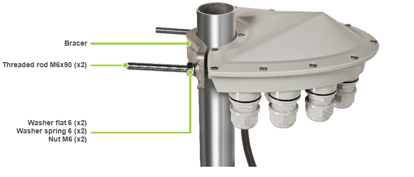
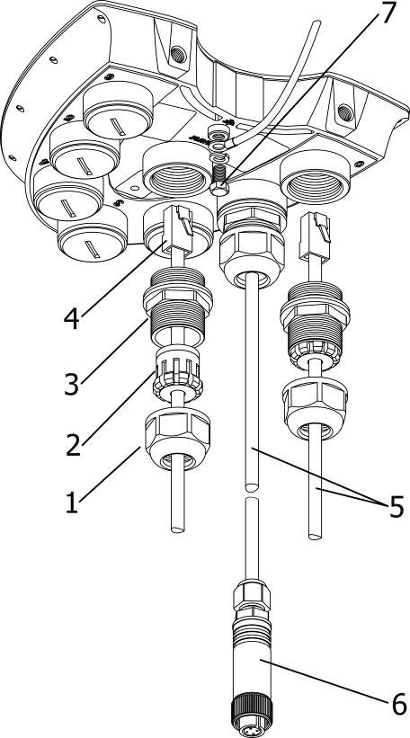
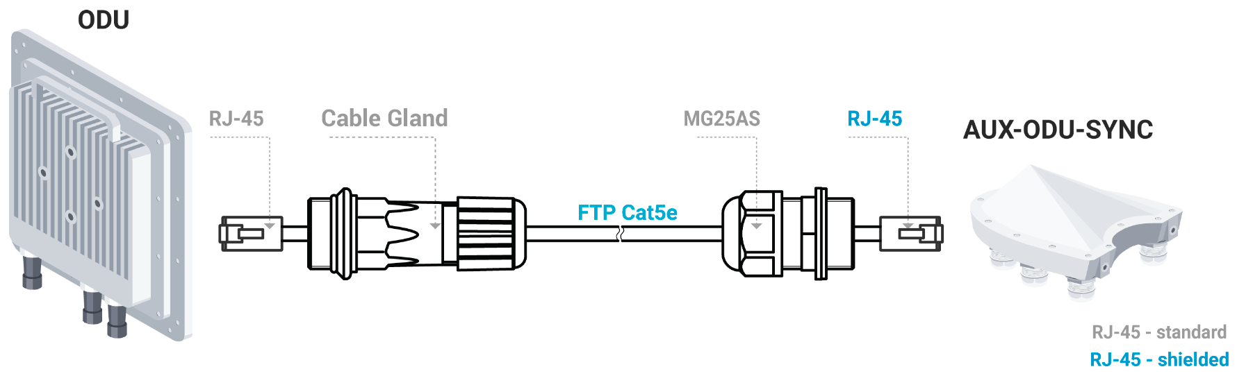
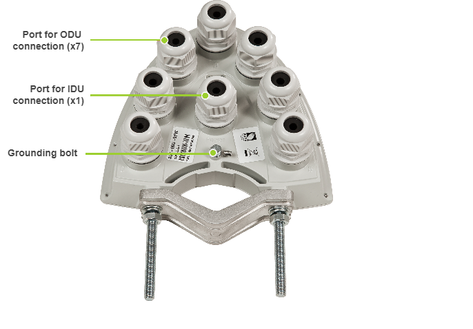
Interfaces and connectors

  • Port 0-6: sync outs (7 RJ-45 connectors to connect to ODU with special cable CAB-SYNC-E)

  • Power: DC input (1 RJ-45 connector)

PoE type

Passive PoE (4,5,7,8 Ethernet pins used)

Size and Weight

180х170х75mm, 0.65kg

Temperature range

  • ODU: -40…+60°С

  • IDU: 0...+40°С

Water and Dust protection

IP66 and IP67

AUX-ODU-SYNC Mounting

AUX-ODU-SYNC can be installed on a pole, using fasteners from the delivery package:

  1. Screw the threaded rod to the unit case.

  2. Tighten the device and the bracer on the pole and fix them by the threaded rod using the nuts and washers as shown at the picture

  3. Attach the grounding cable to the unit case using the grounding bolt.

CAUTION

Missing or bad grounding may leave the unit vulnerable to lightning damage.

AUX-ODU-SYNC Cable gland Assembling

In order to ensure that the cable gland remains sealed under any environmental conditions, please, follow the assembly sequence according to the procedure below:

  1. Put the cable gland nut (1), the split sealing grommet (2) and the cable gland threaded coupling (3) onto the cable

  2. Crimp the connector onto the cable using the crimping tool:

    1. For connection to the port Power terminate the FTP Cat.5e cable with the unshielded RJ-45 connector (4) according to the EIA/TIA-568B. Do not use the shielded RJ-45 connector on this end of the cable as it should be attached on the IDU end (to provide grounding circuit)

    2. For connection to the ports 0-6 use the ready-assembled specialized CAB-SYNC-E (5) cables

  3. Insert the connector of the pre-terminated cable into the corresponding socket until you hear a click

  4. Screw the cable gland threaded coupling (3) into the port and tighten it. Do not apply excessive force

  5. Tighten the sealing grommet (2) by the cable gland nut (1). Do not apply excessive force.

CAUTION

Make sure that the connector is well-crimped. A loose connector can damage the device. Please note that such damage is not covered by the warranty.

CAUTION

Please note that the pressure equalization system in Astra devices is performed via gas exchange through a cable gland and Ethernet cable jacket with a dry room where the power supply is installed. In order to avoid AUX-ODU-SYNC failure due to moisture entering the device, for example, during the pressure drop during the rain, the cable gland assembly requirements should be met and there are should be no cracks in the Ethernet cable jacket.

In addition, you should avoid the Ethernet cable bending near the AUX-ODU-SYNC and pinching with clamps, that can bring to the pressure equalization system fault between the internal volume of the sealed AUX-ODU-SYNC and the external environment during a sudden air temperature change. This may lead to the leakage and device failures.

AUX-ODU-SYNC Connection to ODU

To connect AUX-ODU-SYNC to the units use the ready-assembled specialized CAB-SYNC-E cables which must be ordered additionally. Information about CAB-SYNC-E cables is available at Astra web site in the "Accessories" section.

To connect AUX-ODU-SYNC to ODU insert the RJ-45 connector with cable gland of the CAB-SYNC-E into the corresponding socket of the ODU until you hear a click. Perform the device port insulation with a cable gland as instructed above.